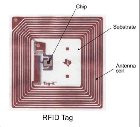
rfid tag design cst Dipole, Loop, and circular/Linear polarized patch antennae are the commonly used RFID antennae. One of the best illustrations of an RFID antenna is a meander dipole antenna, which is modelled in CST Studio Suite software, as shown in Fig.1
Shouldnt be anything to worry about. I have a set of NFC cards myself (all the LOZ amiibo before they released the 4 champions) and never had any problems. When the cards have been programmed, the programmers have copied the .
0 · rfid tag antenna design
1 · rfid antenna design
2 · pifa rfid antenna design
Next, we need to write the digital business card URL on the NFC card. Here’s how to do it. 1. Download an NFC writer app of your choice. We’ve used NFC Tools (available on both the Play Store and App Store) for this tutorial. 2. .
The main parts of the proposed chipless MIMO tag are designed in computer simulation tool . In this study, prototypes of two distinct 8-bit chipless RFID tags operating in 3–6 GHz utilising L-resonators discussed in Section 2 are reported. The chipless tags have been designed using CST Microwave Design Studio and printed on the Roger RT 5880 substrate.The main parts of the proposed chipless MIMO tag are designed in computer simulation tool (CST) and their performance is verified. The detailed descriptions of the component‐level design and their integration to a complete MIMO tag are examined.The design considerations for RFID tag, Impedance matching and PIFA structures are discussed in this paper. Before fabricating the actual tag, the simulation of antenna

Tag performance can be characterized by tag sensitivity (also called threshold POTF, Power on Tag Forward) and tag backscatter (also called POTR, Power on Tag Reverse).Dipole, Loop, and circular/Linear polarized patch antennae are the commonly used RFID antennae. One of the best illustrations of an RFID antenna is a meander dipole antenna, which is modelled in CST Studio Suite software, as shown in Fig.1This article presents a bio-inspired circularly polarized ultrahigh-frequency (UHF) radio frequency identification (RFID) tag antenna for metallic and low-permittivity substances. This tag design is based on a leaf-shaped radiator, two shorting stubs, and slots etched on F4B substrate. The main parts of the proposed chipless MIMO tag are designed in computer simulation tool (CST) and their performance is verified. The detailed descriptions of the component-level design and their integration to a complete MIMO tag are examined.
Abstract: This paper presents the design of a passive RFID tag antenna operating at 2.45 GHz. The electromagnetic simulation software called CST is used for design and simulation. A high gain (5.842dB), a good impedance matching with the microchip (-30.0 dB Return Loss) and a satisfactory read range performance (upto 5 m) was obtained.PIFA RFID Tag Antenna Design and Simulation using CST Microwave Studio. Sudha Surwase, Dr. Ravi Yadahalli, Dr. Shankar Nawale. Abstract: There has been an enormous upsurge in the popularity of RFID (Radio Frequency Identification) systems in recent years. STM electronics has application note AN1806 with detailed description how to design and tune 13.56 antenna. And other tools - search for it. Other companies who manufacture reader and tag IC's likely have it too. In this study, prototypes of two distinct 8-bit chipless RFID tags operating in 3–6 GHz utilising L-resonators discussed in Section 2 are reported. The chipless tags have been designed using CST Microwave Design Studio and printed on the Roger RT 5880 substrate.
rfid tag antenna design
The main parts of the proposed chipless MIMO tag are designed in computer simulation tool (CST) and their performance is verified. The detailed descriptions of the component‐level design and their integration to a complete MIMO tag are examined.
The design considerations for RFID tag, Impedance matching and PIFA structures are discussed in this paper. Before fabricating the actual tag, the simulation of antennaTag performance can be characterized by tag sensitivity (also called threshold POTF, Power on Tag Forward) and tag backscatter (also called POTR, Power on Tag Reverse).
Dipole, Loop, and circular/Linear polarized patch antennae are the commonly used RFID antennae. One of the best illustrations of an RFID antenna is a meander dipole antenna, which is modelled in CST Studio Suite software, as shown in Fig.1This article presents a bio-inspired circularly polarized ultrahigh-frequency (UHF) radio frequency identification (RFID) tag antenna for metallic and low-permittivity substances. This tag design is based on a leaf-shaped radiator, two shorting stubs, and slots etched on F4B substrate. The main parts of the proposed chipless MIMO tag are designed in computer simulation tool (CST) and their performance is verified. The detailed descriptions of the component-level design and their integration to a complete MIMO tag are examined.Abstract: This paper presents the design of a passive RFID tag antenna operating at 2.45 GHz. The electromagnetic simulation software called CST is used for design and simulation. A high gain (5.842dB), a good impedance matching with the microchip (-30.0 dB Return Loss) and a satisfactory read range performance (upto 5 m) was obtained.
rfid antenna design
PIFA RFID Tag Antenna Design and Simulation using CST Microwave Studio. Sudha Surwase, Dr. Ravi Yadahalli, Dr. Shankar Nawale. Abstract: There has been an enormous upsurge in the popularity of RFID (Radio Frequency Identification) systems in recent years.
arduino long range uhf rfid
pifa rfid antenna design

Basic tracking is handled two separate ways: locally via Bluetooth, and remotely via Apple's Find My network. The former requires the Eufy Security app (available for iOS only) and lets you find the SmartTrack Card in your house or immediate environs, . See more
rfid tag design cst|rfid tag antenna design